
Dec 14, 2017
Manufacturing a Soldered Thermistor Using UL1007 24 AWG Hookup Wire
Table of Contents
- Tools and Materials Needed to Manufacture a Soldered Thermistor with UL1007 Hook Up Wire
- Step 1: Cut the UL1007 24 AWG Wire to Length
- Step 2: Tin Dip the Wires to Prepare for Soldering
- Step 3: Solder the Thermistor to Two 24 AWG Wires
- Final Step: Bagging and Tagging the Thermistors as Instructed
- Quality Inspection Report
Tools and Materials Needed to Manufacture a Soldered Thermistor with UL1007 Hook Up Wire
In order to manufacture a soldered thermistor, you will need UL1007 24 AWG hook up wire, the appropriate type of thermistor, lead free solder, a solder iron, a solder tin pot and possibly a wire cutting machine if you’ll be manufacturing the thermistors in bulk quantity. If you have all of the required materials it might make sense for you to manufacture them manually, however buying more than 100 at a time could prove to be cheaper from a fully staffed company that has equipment, LEAN initiatives, processes and procedures already in place.
Step 1: Cut the UL1007 24 AWG Wire to Length
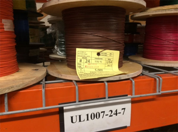
In this case, for this particular thermistor, we’ll be using UL approved 1007 PVC wire with tinned copper strands. Using tinned copper rather than bare copper will help connect the solder with the conductor because the tin coating will slightly melt as the heat is applied at approximately 750°F. When the PVC insulation is removed from both ends it will be clear that the strands either have a tin coating or not. The wire will be put through a Kappa 310 cutting machine to cut an overall length of 6 inches while also removing 0.5 inches of insulation from each end. The manufacturing print for this wire harness indicates that one end will be dipped into tin to prevent the individual strands from fraying and the other end will be attached to the thermistor with solder.
PVC insulated wire with an approval number of UL1007 is tested and approved by Underwriter’s Laboratories as a 300 volt 105°C protection level. For example, bare copper without insulation cannot be exposed to very much heat or voltage without corroding and becoming defective. Therefore, electrical engineers and designers mold PVC insulation around the copper wire to protect it from voltage and heat, among many other things such as environmental conditions as well. A UL stamp of approval is very important as UL is a trusted company that tests and approves various electronic devices for electrical safety and compliance. One would feel much better seeing a UL part number stamped on the wire rather than hearing “my word” that it’s approved for 300 volts.
Step 2: Tin Dip the Wires to Prepare for Soldering
The tin dipping process starts with increasing the temperature of the solder pot, which is a metal cup filled with lead free solder (Tin, hence “Tin Dip”). The production assembler will first examine the loose copper strands to be assured that they are twisted neatly together so that the finished product is neat and straight without any bumps or clumps of solder. If a single copper strand is bend sideways during the dip it will be quite evident afterwards and even deemed a nonconforming product in most cases. Both ends of the wire need to be tin dipped leaving one end completed and preparing the second end for soldering the thermistor.
Lead free, or RoHS compliant, tin and solder have become nearly exclusive in the wire, cable and contract manufacturing industry. Even though some applications require lead based solder for certain reasons, lead has been deemed a dangerous product for people to come in contact with, so most companies have been regulated by governments to remove lead, and all hazardous metals, from their appliances, devices and al materials that humans may come in contact with at any time. Read more on RoHS and REACH compliances for further information on lead and hazardous metals.
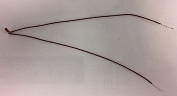
Step 3: Solder the Thermistor to Two 24 AWG Wires
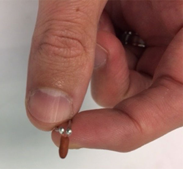
Start by prepping the station with multiple 24 AWG wires, solder, a clamp to hold the wires and a solder iron set to 750°F. Clamp two of the UL1007 24 AWG wires about an inch apart in the rubber clamp and hang the strand of solder close to the clamp. Twist each end of the thermistor to the copper strand of each wire and cut the excess of the thermistor since it will not be needed. Then apply a small bead of solder to adhere the strand of the thermistor to the strand of copper, then repeat the process for the second wire. This completes the process of manufacturing a soldered thermistor to PVC wire before the bagging and labeling process.
The soldering process can be very tedious because the amount of solder applied must be within tolerance and the amount of heat applied cannot burn out the thermistor. Typically, the bead of solder applied cannot be too big or too small because too much solder can be clunky and difficult for the end user to work with, while too little solder can allow the wires to detach in transit or by accident. Leaving the solder iron on the thermistor for too long could cause long term damage to it or completely deem it nonconforming. Leaving that amount of heat applied to the copper conductor could also cause damage to the wire which would be difficult to determine unless you have a background in electrical engineering and continuity testing. Be quick, be efficient and practice before working with customer material or expensive products that might become waste.
Final Step: Bagging and Tagging the Thermistors as Instructed
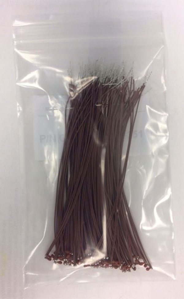
The finished products will be bagged by the hundred with a label on each. The label includes the customer’s part number, revision level, quantity and date. Any additional information supplied by the customer can be incorporated into the label along with any and all inspection reports created during the process of manufacturing.
Quality Inspection Report
A quality inspection report isn’t simply a final-check at the end of the process. Instead, a formal quality process will have a traveler package that follows each step, in order, for the assembler to quality-check and sign after each step is completed. This is referred to as an In-Process quality procedure that can find nonconforming product long before all of the parts are manufactured and long before all of the processes are completed.
For example, after setting up the Kappa 310 cutting machine, the machine operator must sign their name to the report stated that the length is accurate and the insulation strip is completed to the correct measurement. Then they must sign again when the cutting process is complete. Then the next assembler to complete the tin dipping process will do the same, and the soldering staff member will as well. In-Process quality inspections save the company from wasted product and wasted labor when things go wrong, and with human operators, things tend to go wrong every once in a while. Minimizing risk and wasted labor is important for a company to operate efficiently, profitably and at full capacity.